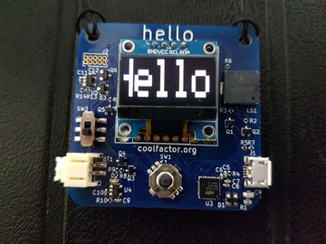
Yes! It’s for your name, your nickname, your callsign, your avatar, your logo, your emotional state, or anything else you might want to advertise to people standing right in front of you.
Electronic badges are a modern staple of hacker camps and conferences, with a wide variety of designs. Many are immensely complicated with network connectivity, apps and other such functionality. But this is a mini badge. It’s small enough to be easy to carry around. It’s not trying to be a phone or a general purpose computer, and it’s not trying to run lots of apps. It’s also not tied to one specific conference or camp. It’s just a badge. It shows your name, in style.
If you have a hello badge and are looking for information on how to put your data on it, here it is.
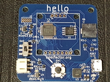
The badge is based on a LPC1115 microcontroller with 64KB of flash memory, and 8KB of RAM. The CPU is an ARM Cortex M0, which is about as simple as ARM-based microcontrollers get nowadays. Alongside the microcontroller is a S25FL064L serial flash chip with 8 megabytes of memory, which is used as a filesystem.
The display is the incredibly common I2C (4 pin) SSD1306-based 0.96" 128x64 pixel OLED that is found pretty much everywhere. It’s a very capable display, and can be pushed far beyond the standard I2C speed limits. Connections are also available for a SPI version of the display, when mounted upside down, as a backup plan in case the I2C wasn’t fast enough. These could be used as spare GPIOs for expansion projects.
For connectivity, there’s a CP2102N USB serial bridge. One of the GPIO pins controls whether the DTR and RTS lines are connected to the reset and bootloader select pins on the microcontroller. This effectively provides a bootloader mode and an application mode, allowing the application to use the hardware handshaking lines for handshaking, and as most terminal programs assert DTR when connected, allows for usage without having to do any special configuration of the terminal software. The CP2102N is programmed to select application mode by default, and a Python script is provided to switch modes for programming the firmware.
There’s a MCP73831 battery charger, which can have its charge current set by the USB interface. A NCP115 voltage regulator supplies current to the rest of the circuit, and is controlled either by the power switch or by the presence of a USB host. This means that the badge can not be switched off while plugged in to USB, and is done this way to make it easier to avoid back-powering the microcontroller from the USB chip.
A navigation button underneath the display provides five button inputs to the microcontroller.
And there’s a piezo element wired across two GPIOs (that share a timer) so that beeps can be generated by driving them in antiphase. Beep.
See the circuit diagram or check out the hardware repository on github for further details.
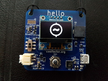
The firmware is capable of displaying images or videos. These are stored in an uncompressed format which matches the memory layout of the display in order to reduce the amount of work that the processor has to do for each frame. Files are stored in a LittleFS filesystem, using the serial flash as underlying storage.
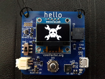
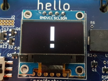
One file is selected as the currently displayed file, and that is continually animated on the display. The firmware uses a timer interrupt to kick off the display update, and then the appropriate routine is given an opportunity to draw the next frame, using a double-buffered scheme. The frame rate is variable and is specified in each media file. If the file can not be opened, an exclamation mark is drawn instead as a visually loud indication that there is a problem.
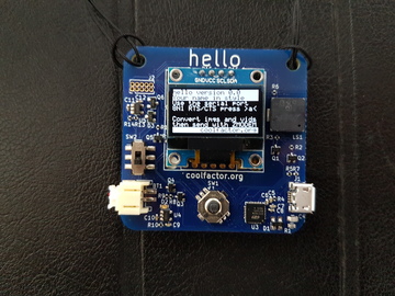
There is a rudimentary command line interpreter which is connected to the serial port. The UART starts off in autobaud mode, and for this to work the first character received must have the first (least significant) bit set. This means that characters such as a, c, e, etc will work, but b, d, f etc will not. While at least one character is present in the command buffer, a chevron > will be displayed on the screen to indicate that the command line is active.
![]()
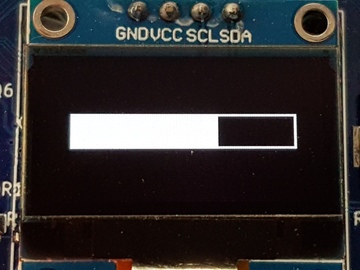
The badge also implements ZMODEM in order to receive files from the host. ZMODEM supplies filename information, so the badge has everything it needs in order to store the file as it’s received. A progress bar is displayed on the badge while a file transfer is in progress.
While displaying a file, the left and right buttons skip to the next/previous file and the up and down buttons alter the screen brightness. But pressing the button brings up a menu.
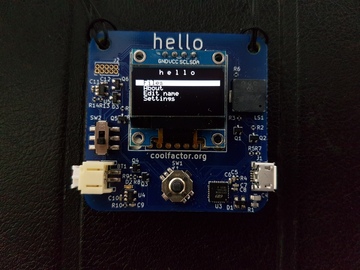
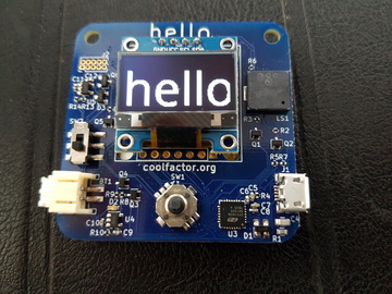
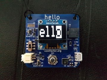
There’s a simple file manager which allows you to select a file to display, but also to delete a file. You can create an image file using the name editor, which allows for simple text input using the navigation button, and creates a scrolling image with a nice retro blocky font.
You can remind yourself of the serial parameters with the About screen, or you can explore the Settings menu to change a few basic parameters.
See the firmware repository on github for further details.
The hello-convert.py script can take text, an image or a series of images and convert it to a file that the badge can understand. Text is rendered to an image using a TrueType font, defaulting to a maximal fit in height (according to the python image library, anyway) although this can be overridden. Image metadata can be specified on the command line, including what to do after scrolling to the end of the image - whether to scroll off the screen and then back on, or whether to change direction. The number of pixels to scroll in each frame is also a configurable option.
Video is provided as a series of images with a common prefix. These are sorted and then concatenated into a video.
For both images and video, the frame rate is also configurable (default: 50fps), as is the frame number at which the display should start when the file is loaded.
ffmpeg can be used to convert most video formats into a series of images.
The hello-uart.py script can switch the badge between application and bootloader modes. It is invoked automatically by make flash, but people using other operating systems might need to run it explicitly.
It’s also capable of reading and writing the configuration EEPROM on the CP2102N chip, and is used for the initial configuration of the hardware in production. This generally does not need to be done again after the initial production.
hello-checksum.py is a simple little utility to compute the EEPROM checksum for the CP2102N chip.
The CP2102N has a considerable amount of data in its configuration block. There is an application note from Silicon Labs which documents most of this, but unfortunately the configuration for GPIO.5 is not present. GPIO.5 is the pin which controls whether the badge is in bootloader or application mode. A certain amount of reverse engineering was required in order to set the default state of GPIO.5.
Fortunately, it was rather easier so set the rest of the configuration parameters. The device description and manufacturer strings were easy to find, and of course they now point to here!
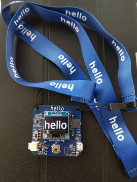
None of this is much use if you can’t wear the badge on your body. I considered 3D printing a case which can be mounted onto clothing with a magnet, but in the end it turned out to be simpler to have a lanyard custom made with the badge name (“hello”) on it, and a string loop on each end. It turns out that while this configuration is available for custom manufacturer, nobody seems to offer double-ended lanyards with string loops as a stock item, so custom printing a logo wasn’t something that would cost any more.
That said, it did take a few round trips to explain to the manufacturers (who do not have English as their first language) that the logo was simply the word “hello”, and that the text “all in lower case” was an instruction for how the text should be written, not the text itself. And that perhaps I didn’t want it written in upper case.
I first had the idea for this project in May. I wanted to get a batch manufactured in time for CCCamp in August. This was rather ambitious as three months is not a long time in which to design the hardware, get a prototype made, fix the issues and get a production run made, while also writing all the software and associated bits and pieces.
In order to minimise the risk of manufacturing problems, I chose to use two different suppliers to make the prototypes. I used the PCB manufacture and assembly services of PCBWay and Elecrow, both reasonably well known in the hobbyist community. For this particular design, PCBWay were a fair bit cheaper, but Elecrow were faster. The PCB does not include the display module and the battery, but everything else was assembled by the factory.
While I was waiting for the first batch I procured a LPC1115 development board and started bringing up the build environment, the firmware and the I2C and display drivers, meaning that when the first prototypes arrived I was well on the way to proving most of the hardware. It took some time to reverse engineer the CP2102N sufficiently to fully configure it in order to prove the application/bootloader switch functionality, and to write the hello-uart.py script in order to be able to fully control the mode and the configuration, but it wasn’t too long before I had some firmware running on the badge. It appeared at first that the power switch wasn’t working and that the circuit would need some further work, but it turned out that some debug code I’d put in to drive the multicolour LED on the LPC1115 development board was supplying enough current through the UART lines to power the CP2102N and to latch up VBUS, which in turn kept the power on. So yes, it’s possible for firmware to fix the power switch.
I set about proving the rest of the hardware at this point - writing a quick and dirty SPI and serial flash driver, driving the beeper from a timer, testing the buttons, etc. And then there was the rest of the power handling - the battery charging, and powering from USB.
Which was where things went a bit wrong - I’d got the wrong pinout for D3, the diode that supplies power from VBUS to the voltage regulator. It’s in a 3 pin package, although only two are connected. This was a problem because without it the badge has to draw its power from the battery charger when it is connected to USB. Fortunately, the diode can be rotated through 120 degrees with the aid of a hot air rework station, and then the circuit works as designed. Naturally this was also fixed in the design files before going to production.
As both manufacturers had correctly assembled the PCBs, I went with the cheaper one for the production run. I still had enough time to have a batch made, with a little bit of contingency, so I placed an order for 200 boards, to supplement the 20 prototypes. Expecting a few breakages in the field, I ordered 250 each of the rest of the components - displays, batteries, lanyards. I also ordered some sticky tape to attach the batteries, and some cheap soldering kits so that people can have a go at attaching the displays themselves. To make it easier to attach the display straight, I 3D printed a jig to hold the display and the PCB in place during soldering.
One downside of the market being flooded with apparently identical display modules is that sometimes they’re slightly different. For example, the batch I received for production had slightly different physical dimensions to the ones I’d prototyped with. This means that the holes don’t quite line up - not a real problem, as the holes were just there is case extra mechanical stability was required, but it turns out that the solder attachment is more than good enough. Unfortunately, that was not the only difference. When I connected a display to a badge, the bottom 8 rows of the display were showing garbage. It turns out that this version of the display module wraps around to the start of screen memory after only 7 out of the 8 pages, so the write never reaches the 8th page. (The memory is organised as 8 pages, each consisting of 8 rows.) The registers which are supposed to control where this wraparound happens did not do anything. I presume this is because the displays I received had a different (and buggy) clone of the SSD1306 display controller. I did find that it was possible to start writing at page 7, and that I could at least cover the whole display this way, and then to tell the display controller that row 56 was actually the top of the display.
I will be selling a little over 200 badges at cost price (€25) at the EMF village at CCCamp 2019. If you can’t be at CCCamp, or you don’t manage to buy one before stocks run out, please let me know that you’re interested, because if enough people say they’re interested I may well do another production run.
Of course, the PCB is open source, so you can always get a few manufactured yourself.